 |
Given all the possible viewing options available for virtual cities, it seems prudent to hedge development towards as many viewing options as possible. We start by extracting our cities into primitive shapes and precisely noting their location in 3-D space using a Cartesian coordinate system we can translate into other popular formats. Architectural primitives include the wall, box, roof, and column. Odd shaped features can be captured as points in three-dimensional space and connected into polygons that define the structure they cover. We store the attributes of each structure in a database and use procedural algorithms to generate the structure according to the requirements of intended use.
Each structure then has materials associated with its presentation. The material can include photographed details which defines a texture or a simple color for covering its extent. We can put the geometry and material information into a database and characterize each record in order to use it flexibly based on a use case. As seen with the popularity of Myspace and Youtube, today's databases are enormous vaults of digital information. Such capacity lets us store multiple versions of each structure, each primitive geometry, and each material. As long as we identify each contribution with identifying characteristics (such as author, size, begin and end year, etc.), we can choose the best representation of our content at the time we put our virtual city together for exploration. We don't have to get too concerned about what best means as it is contextual, but we can build a service that chooses an official version for official use (such as Wikipedia provides for official Wikipedia encyclopedia use).
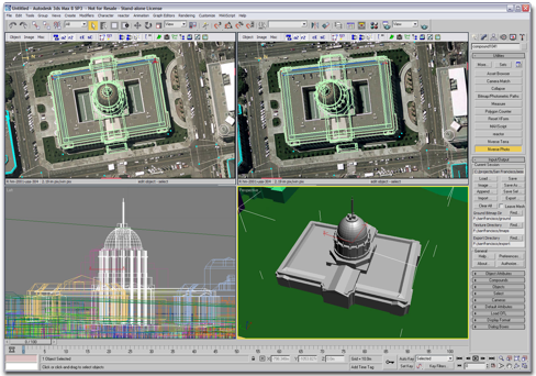
We can use a sophisticated modeling tool which shows us multiple views simultaneously (as in the picture on the left). Or, we can build from scratch using a text editor. Consider a simple example...
|
|
3-D Web History |
Building Virtual Cities |
Viewing Virtual Cities |
Virtual Cities History |
Historical Preservation |
More Links...
Consider the Virtual San Diego presented in Planet 9's virtual city movie. Each of the buildings portrayed consists of polygons created in 3-D space covered with a photorealistic texture. There are tens of file formats we can use to store our models and apply textures. VRML97 is a community-based ISO standard that demonstrates the process. If you get the basic idea behind a VRML97 example, you're ready to consider any other file format where syntax will be the only major difference. X3D is the XML-compliant encoding of VRML97 that includes new features moving forward with the same community.
| |
|
Consider an example in VRML97 and the same representation in X3D. An example of building a virtual city structure
geometry IndexedFaceSet {
	coord Coordinate {
		point [
			1406.5 0 685.5, 1345.5 0 685.5, 1345.5 0 795.5, 1406.5 0 795.5,
			1406.5 7.75 685.5, 1345.5 7.75 685.5, 1345.5 7.75 795.5,
			1406.5 7.75 795.5, 1389 12 783.5, 1389 12 779.5, 1401.5 12 779.5,
			1401.5 12 696.5, 1350.5 12 696.5, 1350.5 12 779.5, 1363 12 779.5,
			1363 12 783.5, 1389 7.8 783.5, 1389 7.8 779.5, 1401.5 7.8 779.5,
 			1401.5 7.75 696.5, 1350.5 7.75 696.5, 1350.5 7.75 779.5,
			1363 7.75 779.5, 1363 7.75 783.5, 1381 10 783.5, 1371 10 783.5,
			1371 10 794.5, 1381 10 794.5, 1381 7.75 783.5, 1371 7.75 783.5,
			1371 7.75 794.5, 1381 7.75 794.5
		]
	}
We start by identifying points that define the vertices of our polygons (the end points of the line segments that we will connect to generate polygons). This is not much different that identifying the dots in a connect the dots coloring book. Our dots are three-dimensional instead of the two-dimensional dots in a coloring book. Each coordinate is separated by a comma. The first vertex (dot) in three-dimensional space used for our building is 1406.5 0 685.5. That is 1406.5 meters to the right of our coordinate reference point (our location 0 0 0), 0 meters high from our coordinate reference point (on the ground, in other words), and 685.5 meters towards us from the reference point (negative third dimension values are away from us from the reference point).
     coordIndex [
          0 1 5 -1, 0 5 4 -1, 1 2 6 -1, 1 6 5 -1, 2 3 7 -1, 2 7 6 -1, 3 0 4 -1,
          3 4 7 -1, 9 8 16 -1, 16 17 9 -1, 17 18 10 -1, 10 9 17 -1, 11 10 18 -1,
          18 19 11 -1, 19 20 12 -1, 12 11 19 -1, 13 12 20 -1, 20 21 13 -1,
          21 22 14 -1, 14 13 21 -1, 15 14 22 -1, 22 23 15 -1, 16 8 15 -1,
          15 23 16 -1, 29 30 26 -1, 26 25 29 -1, 27 26 30 -1, 30 31 27 -1,
          28 24 27 -1, 27 31 28 -1, 30 6 7 -1, 30 7 31 -1
     ]
We then connect our vertices into polygons with each polygon closed by a -1,. The most common polygon is a triangle since all polygons with more than three sides can be reduced to multiple triangles via a simple process (choose a point, connect it with two neighboring points, then connect that same point with the furthest point and its next neighbor, then connect that same point with that last triangle's furthest point and its next neighbor, continue until you've made triangles out of all the points in the polygon). We could just as easily use four points for each polygon (a four-sided polygon is called a quad).
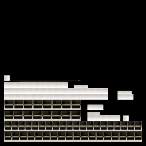
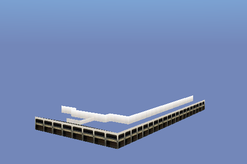
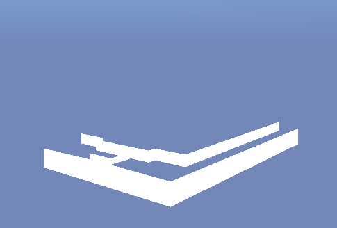
In this example, we make our first triangle out of points 0, 1, and 5 (computer scientists start counting with 0 because they are thinking in terms of relative distance of addresses in computer memory). Point 0 is 1406.5 0 685.5, point 1 is 1345.5 0 685.5, and point 5 is 1345.5 7.75 685.5 which we identify from our list of 3 values that make a three-dimensional point (the commas deliminate points from each other). We now have a triangle that exists in three-dimensional space. Following that logic through the other 31 triangles identified by the coordinate indices, we start to build up a piece of our building. The 32 triangles alone make up the model shown in the top left image.
texture ImageTexture {
     url "./Textures/53343326.jpg"
}
We can texture our model using a image file we've generated in Gimp, Photoshop, or created directly from a digital photograph. We can generate as many separate polygon models as we want and apply one texture to each polygon model. Or, we can get fancy and generate a texture that let's us add material to more than one polygon from a single image. The url field value points to the file relative to the file we are creating for the building model itself. The concept is identical in a 2-D Web page where we use an href field to refer to an image we want to show on our Web page. The middle image to the left shows a more fancy (and more efficient for downloading) texture image that has been prepared in the Gimp, a freely downloadable image manipulation application.
Once we generate a texture and reference it in our model file, we apply the texture to our polygons. In VRML97, we do it with the following text:
texCoord TextureCoordinate {
point [
.03 .03, .03 .096, .03 .102, .03 .169, .03 .175, .03 .241, .03 .247, .03 .313,
.03 .319, .03 .356, .03 .359, .03 .395, .03 .399, .03 .435, .03 .447, .03 .448,
.03 .482, .066 .448, .066 .482, .248 .439, .333 .439, .466 .399, .466 .435,
.506 .399, .506 .418, .551 .175, .551 .241, .551 .247, .551 .313, .551 .447,
.6 .175, .6 .211, .6 .214, .6 .234, .6 .247, .6 .283, .6 .399, .6 .418, .685 .214,
.685 .234, .706 .247, .706 .283, .739 .319, .739 .356, .739 .359, .739 .395,
.805 .319, .805 .356, .805 .359, .805 .378, .822 .175, .822 .211, .842 .175,
.842 .209, .879 .175, .879 .209, .899 .359, .899 .378, .912 .319, .912 .356,
.97 .03, .97 .096, .97 .102, .97 .169
]
}
texCoordIndex [
28 7 6 -1, 28 6 27 -1, 61 1 0 -1, 61 0 60 -1, 26 5 4 -1, 26 4 25 -1, 63 3 2 -1,
63 2 62 -1, 54 55 53 -1, 53 52 54 -1, 59 47 46 -1, 46 58 59 -1, 10 44 45 -1,
45 11 10 -1, 22 13 12 -1, 12 21 22 -1, 8 42 43 -1, 43 9 8 -1, 41 35 34 -1,
34 40 41 -1, 17 18 16 -1, 16 15 17 -1, 31 30 50 -1, 50 51 31 -1, 57 49 48 -1,
48 56 57 -1, 32 38 39 -1, 39 33 32 -1, 24 23 36 -1, 36 37 24 -1, 20 29 14 -1,
20 14 19 -1
]
The generation of our texture materials is similar to the generation of the polygons. We specify coordinates in two-dimensional space that refer to polygons in our texture file. All values are between 0 and 1 because they are relative to the length of the rectangular image sides. The first value is the distance up from the lower left corner of the image (multiple by 100 to get a percentage). The second value is the distance to the right of the lower left corner. A texture coordinate of .03 .03 is a point on the texture 3% from the bottom and 3% from the left border of the image.
The coordinate indices into these points on the image generate polygons on the image similar to how we generated polygons in three-dimensional space for our model. In fact, we require a one to one correspondence of polygons on the texture to polygons in the model. We make 32 triangles out of our texture coordinate indices and apply them to the 32 triangles mad out of our model geometry coordinate indices. The relative index numbers do not have to match (the 0 1 5 -1, is different from the 28 7 6 -1,), but the number of indices (3 in our case) must match exactly (or the viewing program will throw out the extras or complain without continuing to process). The texture processing applies the texture to the left to generate the textured model shown below it. Note how much of the texture space is wasted by black background that is not part of any used texture triangle. There is a trade-off between storage and downloading versus speed of accessing the texture in memory once downloaded. Computer memory prefers to be accessed in powers of two (2, 4, 8, 16, 32, 64, etc.). Textures are usually generated square and with dimensions that align with this power of two concept. |
|
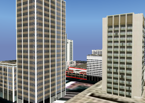
Now you see that a virtual city is comprised of as many model components with textures as you care to include in a model file. The bottom image above shows how our example model component fits into the whole virtual San Diego scene (outlined in red). We only see part of the model since our camera currently sits in front of another building that blocks its view. A smart viewer keeps track of what is in view and only shows the visible polygons. This lets us generate massive virtual cities and yet not overwhelm our local computer's graphics card. We tend to be limited by our CPU memory, not our graphics memory when it comes to polygons. Texture memory on a video card often is our limitation for the visual materials we see.
Virtual city viewers let you add links to your model components. Each building can be in a separate set of coordinates, indices, texture coordinates, and texture indices with a link URL attached. Click on that model set's visualization and you access the content referenced (another higher-resolution model, a Web pages with photography of the inside, a Web page of a menu or catalog, whatever). You start to see how we can have a virtual planet and let links send you to individual virtual cities. We can drill down as far as we want to generate content. Since you control the extent of each model component, you control the linking and the reusability of your virtual city pieces. Reusability becomes key when you want to optimize the behavior of the overall city. Computer memory likes to represent something once and use it multiple times. As a result, virtual city modeling languages let you generate prototypes, primitives, and use definitions. But, each of those really comes down to the process we've demonstrated here. Compare the example above to its representation in X3D below. X3D allows an XML-compliant encoding of a virtual city component. Once we are XML-compliant, we can use all the XML tools out there to edit, streamline, store, and access our virtual cities.
<X3D>
<Scene>
<Transform translation='7334324.683 0 1280987.875' scale='1 1 1'>
<Shape>
<Appearance>
<Material diffuseColor='1.0 1.0 1.0' />
<ImageTexture url=' "./Textures/53343326.jpg" '/>
</Appearance>
<IndexedFaceSet coordIndex='0 1 5 -1, 0 5 4 -1, 1 2 6 -1, 1 6 5 -1, 2 3 7 -1, 2 7 6 -1, 3 0 4 -1,
          	3 4 7 -1, 9 8 16 -1, 16 17 9 -1, 17 18 10 -1, 10 9 17 -1, 11 10 18 -1,
          	18 19 11 -1, 19 20 12 -1, 12 11 19 -1, 13 12 20 -1, 20 21 13 -1,
          	21 22 14 -1, 14 13 21 -1, 15 14 22 -1, 22 23 15 -1, 16 8 15 -1,
          	15 23 16 -1, 29 30 26 -1, 26 25 29 -1, 27 26 30 -1, 30 31 27 -1,
          	28 24 27 -1, 27 31 28 -1, 30 6 7 -1, 30 7 31 -1'
		texCoordIndex='28 7 6 -1, 28 6 27 -1, 61 1 0 -1, 61 0 60 -1, 26 5 4 -1, 26 4 25 -1, 63 3 2 -1,
		63 2 62 -1, 54 55 53 -1, 53 52 54 -1, 59 47 46 -1, 46 58 59 -1, 10 44 45 -1,
		45 11 10 -1, 22 13 12 -1, 12 21 22 -1, 8 42 43 -1, 43 9 8 -1, 41 35 34 -1,
		34 40 41 -1, 17 18 16 -1, 16 15 17 -1, 31 30 50 -1, 50 51 31 -1, 57 49 48 -1,
		48 56 57 -1, 32 38 39 -1, 39 33 32 -1, 24 23 36 -1, 36 37 24 -1, 20 29 14 -1,
		20 14 19 -1'>
<Coordinate point='1406.5 0 685.5, 1345.5 0 685.5, 1345.5 0 795.5, 1406.5 0 795.5,
		1406.5 7.75 685.5, 1345.5 7.75 685.5, 1345.5 7.75 795.5,
		1406.5 7.75 795.5, 1389 12 783.5, 1389 12 779.5, 1401.5 12 779.5,
		1401.5 12 696.5, 1350.5 12 696.5, 1350.5 12 779.5, 1363 12 779.5,
		1363 12 783.5, 1389 7.8 783.5, 1389 7.8 779.5, 1401.5 7.8 779.5,
 		1401.5 7.75 696.5, 1350.5 7.75 696.5, 1350.5 7.75 779.5,
		1363 7.75 779.5, 1363 7.75 783.5, 1381 10 783.5, 1371 10 783.5,
		1371 10 794.5, 1381 10 794.5, 1381 7.75 783.5, 1371 7.75 783.5,
		1371 7.75 794.5, 1381 7.75 794.5'/>
<TextureCoordinate point='.03 .03, .03 .096, .03 .102, .03 .169, .03 .175, .03 .241, .03 .247, .03 .313,
		.03 .319, .03 .356, .03 .359, .03 .395, .03 .399, .03 .435, .03 .447, .03 .448,
		.03 .482, .066 .448, .066 .482, .248 .439, .333 .439, .466 .399, .466 .435,
		.506 .399, .506 .418, .551 .175, .551 .241, .551 .247, .551 .313, .551 .447,
		.6 .175, .6 .211, .6 .214, .6 .234, .6 .247, .6 .283, .6 .399, .6 .418, .685 .214,
		.685 .234, .706 .247, .706 .283, .739 .319, .739 .356, .739 .359, .739 .395,
		.805 .319, .805 .356, .805 .359, .805 .378, .822 .175, .822 .211, .842 .175,
		.842 .209, .879 .175, .879 .209, .899 .359, .899 .378, .912 .319, .912 .356,
		.97 .03, .97 .096, .97 .102, .97 .169'/>
</IndexedFaceSet>
</Shape>
</Transform>
</Scene>
</X3D>
Hopefully, you recognize our pieces from the VRML97 syntax review above. The node and field names are the same in both languages. A couple of things of interest specific to the X3D (which were not included in the VRML97 overview). We've added a transformation to move our model component to a unique place on Earth. The 7334324.683 0 1280987.875 translation references 7334324.683 meters from 0 longitude along the equator, meters altitude (San Diego being near sea level), and 1280987.875 meters north from the equator. We can use a transform to scale our model component (1 1 1 means no scaling as the values are multiplicative of each dimension x, y, and z). We can define a material color (the diffuseColor is the base color it appears to the eye) which would blend with our texture coloring. We can investigate the X3D ISO standard specification to add all kinds of additional features to our base model component.
There are many capable 3-D virtual city modeling tools. 3D Studio Max and Maya are professional tools that export to many popular 3-D model file formats like X3D. The Flux Studio let's you build with a tool specifically generated for VRML97 and X3D content. Google SketchUp lets you quickly generate models, save them to the popular .3DS format and then convert to X3D with any of the other tools. Behind the scenes, polygons and textures are being stored to comprise the model components. |
|